


Close
Online message
If you have any needs, please leave a message and we will contact you as soon as possible。

 601100
Specifications: 10 to 27
Pressure: up to 350 bar
Flow: up to 600 L/min
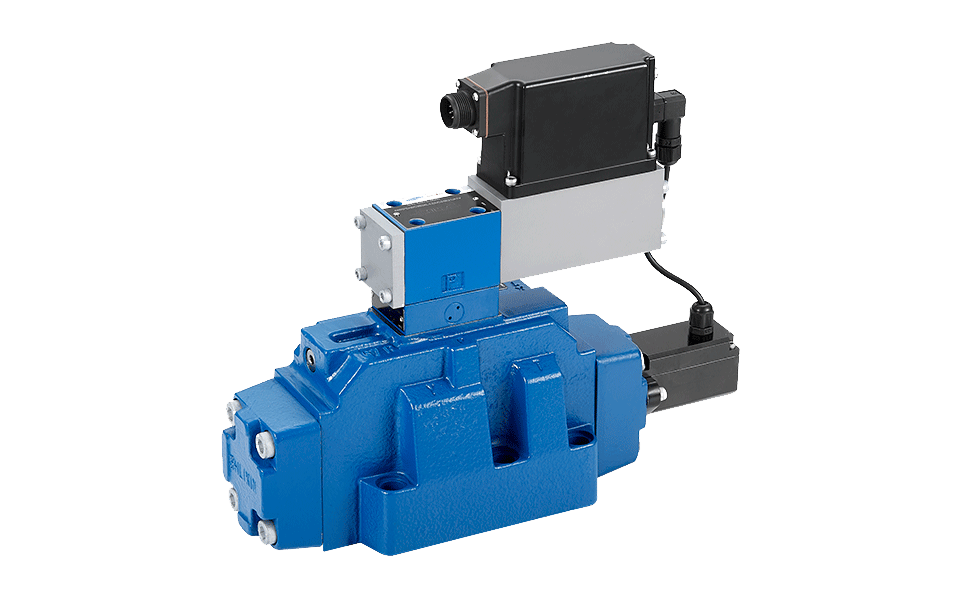
• Pilot valve NG 6, equipped with control spool and sleeve, reliable servo performance, solid structure, unilateral operation, 4/4 power off in Fail-safe function position
• Displacement sensor with metal cover (Lvdt DC/DC)
• The main stage has position feedback function, reliable servo performance
• Pilot operated 4/3-servo directional valve NG10 ~ NG 27
| General | NG10 | NG16 | NG25 | NG27 | ||
| Design | Spool type valve, pilot operated | |||||
| Construction | Servo solenoid directional control valve NG6, | |||||
| with position controller for pilot valve and main stage | ||||||
| Type of mounting | Subplate, mounting hole configuration NG10...27 to ISO 4401-... | |||||
| Installation position | Optional | |||||
| Ambient temperature range | ℃ | –20...+50 | ||||
| Weight | kg | 8.35 | 10 | 18 | 18 | |
| Vibration resistance, test condition | Max.25g, shaken in 3 dimensions (24 h) | |||||
| Hydraulic (measured with HLP 46, ϑoil = 40℃ ±5℃ ) | ||||||
| Pressure fluid | Hydraulic oil to DIN 51524...535, other fluids after prior consultation | |||||
| Viscosity range | Recommended | mm2/s | 20...100 | |||
| Max. permitted | mm2/s | 10...800 | ||||
| Maximum permissible degree of contamination of pressure fluid. Purity class to ISO 4406 (c) | Class 18/16/13 1) | |||||
| Flow direction | See symbol | |||||
| Nominal flow at ∆ p = 5 bar per notch 2) | L/min | see ordering code | ||||
| Max. working pressure | Ports P, A, B External control oil inlet | bar | 350 | 350 | 350 | 280 |
| Ports P, A, B Internal control oil inlet | bar | 280 | ||||
| Ports T, X, Y | bar | 250 | ||||
| Min. control oil pressure in "pilot stage" | bar | 10 | ||||
| Qmax | L/min | 170 | 450 | 900 | 1000 | |
| QN pilot valve Δp = 35 bar | L/min | 4 | 12 | 24 | 24 | |
| Leakage of pilot valve at 100 bar | L/min | <0.18 | <0.35 | <0.5 | <0.5 | |
| Leakage of main stage(symbols "E") at 100 bar | L/min | <0.25 | <0.4 | <0.6 | <0.6 | |
| Static/Dynamic | ||||||
| Hysteresis | % | < 0.1, scarcely measurable | ||||
| Manufacturing tolerance for Qmax | % | ≦ 10 | ||||
| Response time for signal change | at X = 100 bar | 0...100 % | 25 | 26 | 32 | 32 |
| 0...10 % | 14 | 15 | 18 | 18 | ||
| at X = 10 bar | 0...100 % | 85 | 80 | 120 | 120 | |
| 0...10 % | 50 | 30 | 50 | 50 | ||
| Switch-off behavior | After electrical switch-off: pilot valve in fail-safe. Main stage moves to spring-centered "mid position" | |||||
| Thermal drift | Zero point displacement < 1% at ΔT = 40℃ | |||||
| Zero adjustment | Adjustable ±5% via valve amplifier | |||||