


Close
Online message
If you have any needs, please leave a message and we will contact you as soon as possible。

 601100
Specifications: 25~100
Pressure: to 420 bar
Nominal flow: up to 8000 L/min
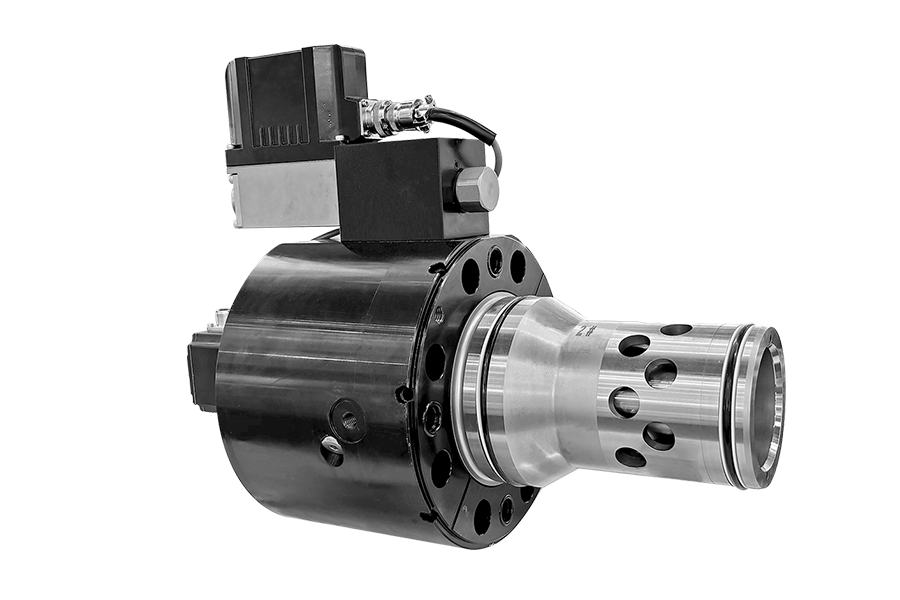
Pilot operated two-way proportional servo directional valve, main valve core with electrical position feedback
The pilot valve adopts a servo level performance spool valve sleeve structure
Voice coil motor
Extremely fast step response
Flow direction B to A and A to B
With integrated electronics
Cavity and mounting pattern according to ISO7368
Typical applications:
-Injection molding
-Die-casting machines
-General presses
| General | ||||||||||||
| Size | 25 | 32 | 40 | 50 | 63 | 80 | 100 | |||||
| Weight | Without shut-off valve .../...K or .../...L | kg | 8.5 | 11.2 | 17.3 | 24.6 | 47 | 74 | 110 | |||
| With shut-off valve .../...WK or .../...WL | 9.8 | 12.5 | 18.6 | 25.9 | 60 | 87 | 123 | |||||
| Installation position | Any, preferably horizontal | |||||||||||
| Storage temperature range ℃ | –20 to +80 | |||||||||||
| Ambient temperature range ℃ | –20 to +50 | |||||||||||
| Sine test according to EN 60068-2-6 | 10 to 2000Hz/ max. of 10g/ 10 cycles/ 3 axes | |||||||||||
| Noise test according to EN 60068-2-64 | Size (NG) 25-40 | 20 to 2000Hz/ 10gRMS /30 g peak /30min /3 axes | ||||||||||
| Size (NG) 50-100 | 20 to 2000Hz/ 10gRMS /30 g peak /24h /3 axes | |||||||||||
| Transport shock according to EN 60068-2-27 | 15g/ 11ms/ 3 axes | |||||||||||
| Hydraulic (measured with HLP32, ϑoil =40℃ ±5℃ ) | ||||||||||||
| Max. operating pressures | Ports A, B, SP | bar | 420 | |||||||||
| Pilot control valve port X | 350 | |||||||||||
| Port Y | 35 | |||||||||||
| Rated flow at Δp = 5bar | Design ...S...L (linear) | L/min | 500 | 800 | 1200 | 2000 | 3600 | 4500 | 8000 | |||
| Design ...S...R (linear with progressive fine control range) | - | 600 | 850 | 1400 | 3200 | 3900 | 6800 | |||||
| Pilot valve pressure | bar | > 140 | ||||||||||
| Max. pilot flow at 140bar pilot pressure | L/min | 23 | 30 | 40 | 40 | 70 | 80 | 100 | ||||
| Leakage of pilot valve at P = 100bar | mL/min | ≤ 400 | ||||||||||
| Hydraulic fluid | Mineral oil (HL, HLP) to DIN 51524 | |||||||||||
| Hydraulic fluid temperature range | ℃ | –20 to +80; preferably +40 to +50 | ||||||||||
| Viscosity range | mm2/s | 20 to 380; preferably 30 to 45 | ||||||||||
| Max. permissible degree of contamination of the pressure fluid is to IS0 4006 (c). | Pilot control valve | Class 18/16/13 | ||||||||||
| Main valve | Class 20/18/15 | |||||||||||
| Hysteresis | % | ≤ 0.1 | ||||||||||
| Response sensitivity | % | ≤ 0.05 | ||||||||||
| Response time 0~100% step signal | ms | 10.5 | 12 | 14 | 20 | 17 | 23 | 28 | ||||
| Frequency response (Δp>140bar;±5% signal) | Amplitude -3dB | Hz | 95 | 80 | 74 | 66 | 52 | 46 | 41 | |||
| Phase -90° | 68 | 63 | 59 | 52 | 56 | 51 | 47 | |||||
| Electric | ||||||||||||
| Duty ratio | % | 100 | ||||||||||
| Supply voltage / ripple | VDC | Direct voltage 22 to 30, electric shut-off at <19, ripple <5% effective, surge free | ||||||||||
| Current consumption max. | A | 3.5 | ||||||||||
| Pre-fusing | A | 4.0, medium lag | ||||||||||
| Input signal: A1 | Voltage | V | 0 to +10, ripple < 0.01%, effective, surge free | |||||||||
| Impedance | kΩ | 100 | ||||||||||
| Input signal: F1 | Current | mA | +4 to 20, ripple < 0.01% effective, surge free, < 3.6mA=disable, >3.8mA=enable | |||||||||
| Impedance | Ω | < 250 | ||||||||||
| Diagnostic signal | Voltage | V | 0 to +10, rated max. 5mA | |||||||||
| Enable signal | V | 5 to 30, Ri = > 8kOhm | ||||||||||
| Electrical connection | 6+PE,plug-in connector in accordance with DIN EN 175201-804 standard | |||||||||||
| Protection class of the valve according to EN60529 | Ip65 | |||||||||||